Technical Information
Why A Lightning System Inspection Reduces Risk:
The fundamental principle in lightning protection is to provide a path whereby lightning energy can enter the earth without causing loss of life or damage to property. A properly functioning lightning protection system will provide a low impedance path to ground where lightning energy can be safely dissipated into the earth.
The conductive path offered by the lightning protection system should be the path preferred by lightning current in preference to all other alternative paths presented by the building construction materials and furnishings. This helps confine the lightning discharge energy to the lightning protection components, which are designed to be unaffected by the heat and mechanical forces produced by the discharge.
The Aging Process
 All components of a lightning protection system deteriorate over time. This is especially true for those components which are buried in the earth such as ground rods and other elements of the grounding system. Eventually, soil moisture, salt, and temperature will combine to deteriorate buried ground rods and their connections. This deterioration will cause the ground resistance between the lightning protection system and the earth to increase. When the ground resistance becomes too large, lightning currents will find an alternative path to ground, which will put the building at risk for damage.
Measurements Are Essential
Some components of the lightning protection system are hidden behind walls or buried in the ground. These components cannot be visually inspected for aging, deterioration, or wear. These concealed elements must be measured to determine their condition. The measurement data must then be tracked over time to know when end-of-life has been reached and replacement should be made.
ICP Lightning Inspections Include:

| Item | Description | Inspection | |
|---|---|---|---|
| 1 |  |
Air Terminals: Air terminals serve as receptors for lightning strikes. These must be properly spaced and have no loose connections. |
|
| 2 |  |
Cable Fasteners: Cable fasteners secure lightning cables to the support structure. These fasteners must be properly spaced and remain securely fastened to ensure there is no undue sag in the cable. |
|
| 3 |  |
Thru Roof Connectors: Thru-roof connectors allow a conductive path to be provided through a roof or vertical wall while maintaining a water-tight seal. These connectors must remain securely fastened to avoid leakage. |
|
| 4 |  |
Down Conductors: These cables carry lightning currents between the air terminals and the grounding electrodes. They are often concealed behind walls and not accessible for visual inspection. Consequently their integrity must be ascertained through measurement. See Continuity Measurement below. |
|
| 5 |  |
Inspection Wells: Inspection wells allow visual inspection of the ground rod clamp and also provide access for ground resistance measurements. Ground rods must be properly sized and clamps must be listed for use in lightning protection systems. Clamps must remain tightly connected to the rod and cable. |
|
| 6 |  |
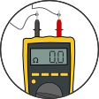
Continuity Measurements: Continuity measurements test the electrical integrity of concealed portions of the lightning cables. This data is critical to ensuring there are no breaks in the cables. Continuity tests also verify proper bonding between the lightning protection system and other grounding systems. |
|
| 7 |  |
Ground Resistance: Ground resistance measurements track degradation of the grounding system over time. Measurements are taken on individual electrodes, the lightning protection system as a whole, and the overall building system ground, which may include electrical and communication system grounds. Measurement data is critical in determining when maintenance or replacement of grounding system components is needed. |
|
| 8 |  |
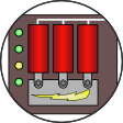
Surge Suppression: Surge suppression modules are checked to ensure there is no visual damage and status indicators are operational. |
Inspection + Correction = Protection